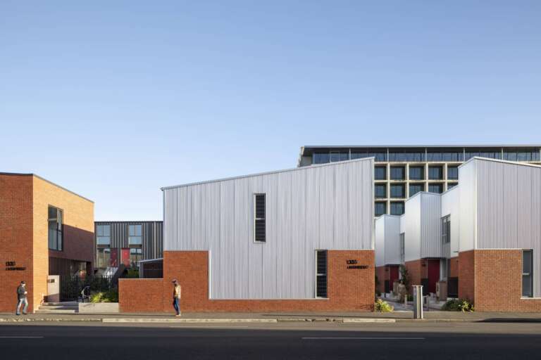
Corrugate Roofing Cladding Grey Friars

Corrugate

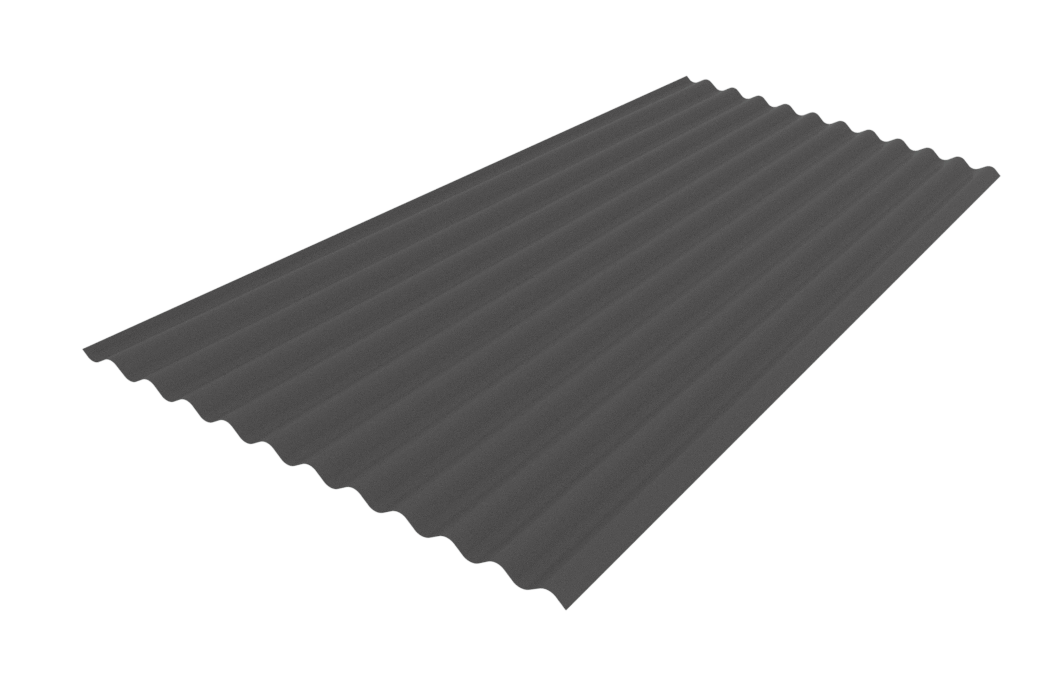
Corrugate roofing is a firm favourite with Kiwis because of its truly classic look that is great on all different styles of building. Used for both roofing and cladding, you’ll never go wrong with classic Corrugate.
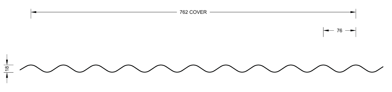
  • Product Details
    • Min Pitch
    • Rib TypeLow
    • Ribs per sheet11.5
    • Cover width762mm
    • Sheet width851mm
  • Suitable For
    Residential
    Light commercial
    Commercial
  • Manufactured In
    Whangarei, Auckland, Hamilton, Wellington, Christchurch, Dunedin, Invercargill

Overview

Corrugate Performance
 

Corrugate is a firm favourite with Kiwis because of its truly classic look that is great on all different styles of building. Used for both roofing and cladding, you’ll never go wrong with classic Corrugate.

Cover (mm)
Minimum Pitch
Cover (mm)
762
Minimum Pitch
8º (approx. 1:7)

All dimensions given are nominal

Sheet Tolerances
Cover: ± 5mm - Sheet length: +10mm, - 0mm (steel)

Cover: +10mm, -15mm – Sheet length: +0mm, -15mm (aluminium)

Material Cladding Testing and Performance
Material Options
Steel
Steel
Steel
Aluminium H36
Duraclad® GRP
Thickness (BMT) mm
Steel
0.40
Steel
0.55
Steel
0.75
Aluminium H36
0.90
Duraclad® GRP
1.7
Nominal weight / lineal metre (kg/m) options
Steel
3.17
Steel
4.27
Steel
N/A
Aluminium H36
2.28
Duraclad® GRP
3.0
Drape curved – min. radius (m)
Steel
12
Steel
10
Steel
N/A
Aluminium H36
10
Duraclad® GRP
8
(1) Purlin spacings for drape curving (m)
Steel
0.800
Steel
10
Steel
N/A
Aluminium H36
1.1
Duraclad® GRP
0.900
(2) Machine roll curved - min. radius (mm)
Steel
450
Steel
450
Steel
N/A
Aluminium H36
450
Duraclad® GRP
N/A
(3) Unsupported overhang (mm)
Steel
100
Steel
150
Steel
N/A
Aluminium H36
150
Duraclad® GRP
100

(1) Recommended maximum purlin spacing at minimum radius

(2) N/A

(3) Based on 1.1kN point load support, but not intended for roof access.

N/A – not available

Roll-forming facility location: Whangarei, Auckland, Hamilton, Wellington, Christchurch, Dunedin and Invercargill 


Roll curving facility location: Hamilton, Christchurch, Dunedin and Invercargill 


Manufacturing location for DuraClad®: Auckland 

Sheet lengths: Corrugate® is custom run to order. 

Where long sheets are used consideration must be given to: 

  • Special transportation licences for sheets over 25m
  • Site access for special lifting equipment 
  • Fixing techniques to accommodate thermal expansion.

Load Span Table

Corrugate Limit State Load / Span Capacity

(span in mm, distributed serviceability loads in kPa)

G550 Steel 0.40mm
Unrestricted Access / Roof
Restricted Access / Roof
Non-Access / Roof or Wall
Unrestricted Access / Roof
End Span
Internal Span
Serviceability
End Span
Internal Span
Serviceability
Restricted Access / Roof
End Span
400
500
700
800
Internal Span
600
800
1000
1200
Serviceability
4.0
3.2
2.5
2.0
Non-Access / Roof or Wall
End Span
900
1000
Internal Span
1400
1500
Serviceability
1.6
1.4
G550 Steel 0.55mm
Unrestricted Access / Roof
Restricted Access / Roof
Non-Access / Roof or Wall
Unrestricted Access / Roof
End Span
Internal Span
Serviceability
End Span
600
Internal Span
900
Serviceability
4.4
Restricted Access / Roof
End Span
600
700
900
1000
Internal Span
1000
1100
1300
1500
Serviceability
4.0
3.7
3.2
2.8
Non-Access / Roof or Wall
End Span
1100
1200
1300
Internal Span
1600
1800
1900
Serviceability
2.6
2.2
2.0
5052 H36 Aluminium 0.70mm
Unrestricted Access / Roof
Restricted Access / Roof
Non-Access / Roof or Wall
Unrestricted Access / Roof
End Span
Internal Span
Serviceability
End Span
Internal Span
Serviceability
Restricted Access / Roof
End Span
500
Internal Span
800
Serviceability
1.4
Non-Access / Roof or Wall
End Span
600
800
1000
Internal Span
900
1200
1500
Serviceability
1.3
1.1
0.8
5052 H36 Aluminium 0.90mm
Unrestricted Access / Roof
Restricted Access / Roof
Non-Access / Roof or Wall
Unrestricted Access / Roof
End Span
Internal Span
Serviceability
End Span
500
Internal Span
800
Serviceability
3.5
Restricted Access / Roof
End Span
600
800
Internal Span
900
1200
Serviceability
3.2
2.2
Non-Access / Roof or Wall
End Span
900
1000
1200
Internal Span
1300
1500
1800
Serviceability
2.0
1.7
1.3
Duraclad®1.7mm (Note 4)
Unrestricted Access / Roof
Restricted Access / Roof
Non-Access / Roof or Wall
Unrestricted Access / Roof
End Span
Internal Span
Serviceability Ultimate
End Span
Internal Span
Serviceability Ultimate
N/R
N/R
Restricted Access / Roof
End Span
600
Internal Span
900
Serviceability Ultimate
4.5
Non-Access / Roof or Wall
End Span
700
800
900
Internal Span
1000
1200
1400
Serviceability Ultimate
4.1
2.3
1.6
Notes
  1. In Restricted Access Roof and Non-Access Roof & Wall applications, spans exceeding the maximum values shown should not be used. The maximum spans for Restricted Access Roofs are based on static point load testing as a guide and are further limited by practical experience of roof performance under dynamic foot traffic loads. For Non-Access Roof & Wall applications, the maximum spans are limited to ensure satisfactory appearance for wall cladding.
  2. Loads given are based on 5 screw fasteners/sheet/purlin.
  3. Loads given are limited to a maximum of 4.5 kPa. If design requirements exceed this limit, contact Dimond for specific advice.
  4. Duraclad®
    – Serviceability Limit State loads are not applicable to the Duraclad® material, as it does not experience permanent deformation.
    – System must include Safety Mesh if intended for use as a Restricted-Access roof. Refer Section 2.2.1.8 of Technical Manual.
  5. N/R = not recommended.
  6. End span capacities given in this table are based on the end span being 2:3 ratio of the internal span.
  7. Design Criteria for Limit State Capacities
    1. Serviceability Limit State (SLS Design)
      No deflection or permanent distortion that would cause unacceptable appearance, side lap leakage or water ponding, due to foot traffic point loads, inward or outward wind loads or snow loads.
    2. Ultimate Limit State (ULS Design)
      No pull through of fixings or fastener withdrawal resulting in sheet detachment due to wind up-lift (outward) loads.
  8. System Design
    The span capacity of the roofing or cladding profile is determined from the Load Span Table, using the section of the chart appropriate to the grade and type of material, and the category of serviceability selected from the two categories above. Serviceability loads have been derived by testing according to NZMRM procedures. To obtain an ultimate limit state load, we recommend factoring the serviceability load by 1.4 in line with NZMRM guidelines. Note: The capacities given do not apply for cyclone wind conditions.

    Serviceability Requirements
    While these categories are provided for design guidance to meet the serviceability limit state criteria, foot traffic point load damage may still occur if point loads are placed carelessly.

    Service Category
    Refer to MRMCOP 3.7.4 Roof Traffic. The designer must consider the degree and type of foot traffic expected on a roof. The following requirements are subjective standards and must be considered in line with customer expectations, building use, and type. More robust design than specified below (such as reducing purlin spacing or adding protection from mechanical action) is required for roofs that are regularly accessed, used as staging by subsequent trades, or areas adjacent to access points, particularly step-down access.
     
  9. Wind Pressure Guide
    As a guide for non-specific design the following S.L.S. design loads in accordance with the MRM Roofing Code of Practice can be used for buildings less than 10m high, otherwise AS/NZS 1170.2 should be used
    Low wind zone = 0.68kPa, Medium wind zone = 0.93kPa, High wind zone = 1.32kPa, Very high wind zone = 1.72kPa and Extra high wind zone = 2.09kPa.

Fasteners

Fasteners 

The durability of the fasteners should equal or exceed that of the material being fastened, and the fastener metal or coating must be compatible with the cladding material if in contact. Refer to NZS E2/AS1 table 20 for compatibility requirements. 

The minimum embedment of 30mm is the requirement for screws fixing into timber and minimum of three threads to pass through steel. When fastening through cavity battens, thermal break materials etc ensure the length of the screw is increased to accommodate the extra material

Common Fastener Lengths* – Roof Cladding - Crest Fixed
Cladding Material
Timber Purlins (m)
Steel Purlins/Grits up to 4.5mm (minimum 3 threads) (mm)
(1,2) Load Spreading Washers (LSW) (When required)
Steel
Timber Purlins (m)
TT 12g x 55 with neo
Steel Purlins/Grits up to 4.5mm (minimum 3 threads) (mm)
ST 12g x 35 with neo
(1,2) Load Spreading Washers (LSW) (When required)
Steel with 30mm EPDM washer
Aluminium
Timber Purlins (m)
TT 12g x 55 Alutite with neo and LSW TT 12g x 50 304 stainless steel with neo and LSW
Steel Purlins/Grits up to 4.5mm (minimum 3 threads) (mm)
ST 12g x 35 304 stainless steel with neo and LSW
(1,2) Load Spreading Washers (LSW) (When required)
Aluminium with 30mm EPDM washer

*- Class 5 fasteners are recommended with steel-based material. 

(1) – When using LSW increase fastener length by 10mm 

(2) - When using LSW pre-drill a 10mm oversized hole to accommodate the EPDM washer

Common Fastener Lengths* – Wall Cladding – Pan Fixed
Cladding Material
Timber Dwangs/Nogs (mm)
Steel Girts up to 2.5mm (mm)
Steel Direct Fix
Timber Dwangs/Nogs (mm)
TT 12g x 40 with neo washer
Steel Girts up to 2.5mm (mm)
ST 12g x 20 with neo washer
Steel On 20mm (nom.) Cavity Batten
Timber Dwangs/Nogs (mm)
TT 12g x 55 with neo washer
Steel Girts up to 2.5mm (mm)
ST 12g x 35 with neo washer
Aluminium Direct Fix
Timber Dwangs/Nogs (mm)
TT 14g x 35 Alutite with neo washer
Steel Girts up to 2.5mm (mm)
**ST 12g x 25 304 stainless steel with neo washer
Aluminium On 20mm (nom.) Cavity Batten
Timber Dwangs/Nogs (mm)
TT 14g x 55 Alutite with neo washer
Steel Girts up to 2.5mm (mm)
**ST 14g x 50 304 stainless steel with neo washer

*- Class 5 fasteners are recommended with steel-based material.

**Stainless steel fasteners require to be separated from aluminium.

Use in serviceability categories (1) or (2) can allow the reduction of fasteners to an average of 2 screw fasteners/sheet/purlin. 

If this is done, the distributed load capacities given in the chart should be reduced using a multiplying factor of 0.5. 

Long spans may require the specification and use of side lap stitching screws – see Section 2.3.2C Installation Information: Layout and Fastening. 


Design Example


Restricted access roof, 0.55mm G550 steel Corrugate has a maximum end span of 1000mm and a maximum internal span of 1500mm. The following distributed load capacities apply

5fasteners/sheet
3 fastener/sheet
End Span
5fasteners/sheet
1000mm
3 fastener/sheet
1000mm
Internal Span
5fasteners/sheet
1500mm
3 fastener/sheet
1500mm
Serviceability
5fasteners/sheet
2.8kPa
3 fastener/sheet
1.7kPa

Fastener Layout Options

Corrugate roofing fastener diagram
Corrugate roofing fastener diagram 2

Inspiration

Corrugate is a firm favourite with Kiwis because of its truly classic look that is great on all different styles of building. Used for both roofing and cladding, you’ll never go wrong with classic Corrugate.
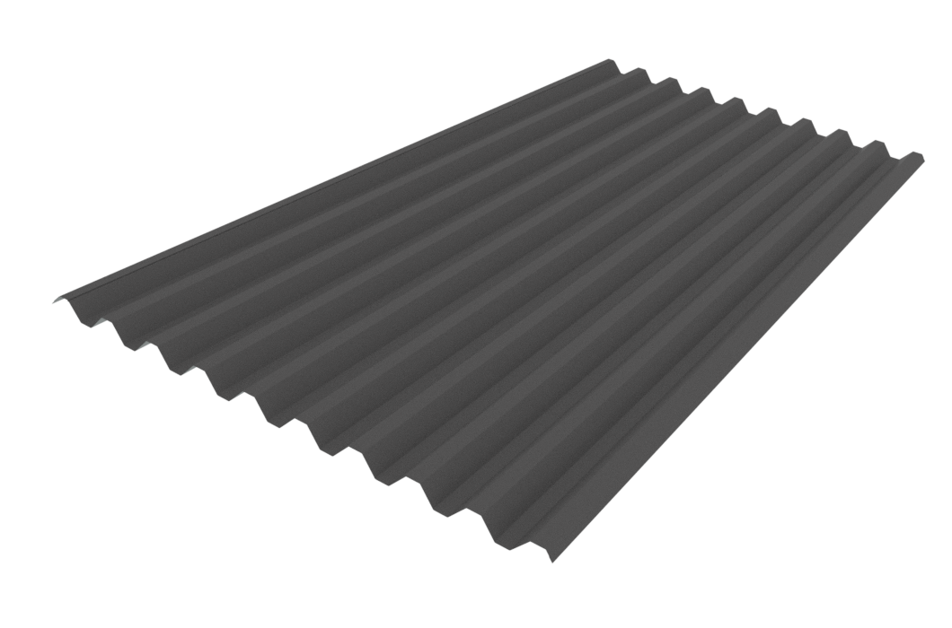
 

DP955 St Hildas collegiate

A Visual & Performing Arts Centre That Lives Up to its Name

Hi Five, DP955®
Profile
Hi Five
Cladding
DP955®
Colour
Pacific White, Sandstone Grey
Location
Dunedin
Architect/Designer
Dwelling Architectural Design
Installer
Ray Ferguson Roofing Limited

Downloads

Product Drawings

Filters

  • Active Filters ()

  • Drawing Type

  • Document Format

  • Commercial Drawings9 Files
    • Roofing3 Files
      • Corrugate - Commercial Drawing
        Drawing
    • Horizontal Cladding3 Files
      • Corrugate - Horizontal Cladding
        Drawing
    • Vertical Cladding3 Files
      • Corrugate - Vertical Cladding
        Drawing
  • Residential Drawings9 Files
    • Roofing3 Files
      • Corrugate - Residential Drawing
        Drawing
    • Horizontal Cladding3 Files
      • Corrugate - Horizontal Cladding
        Drawing
    • Vertical Cladding3 Files
      • Corrugate - Vertical Cladding
        Drawing
  • Corrugate - Technical Statement
    Technical Statement
  • Corrugate - Installers Guide
    Installers Guide