
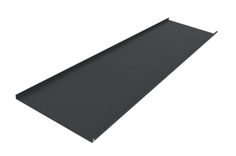
Eurotray® Angle Seam
Looking to add interest into your design or project? Consider the bolder look that Eurotray® Angle Seam offers. This member of the Eurotray® family lends itself well not only as a striking roofing profile - but as an exceptional wall cladding solution as well. In cladding situations, Angle Seam can be run both vertically or horizontally. Angle Seam can also be concave curved.
- Product Details
- Min Pitch3º
- Rib TypeConcealed Clip
- Ribs per sheetTray
- Suitable ForResidential
Light Commercial
Commercial - Manufactured InAuckland, Christchurch, Invercargill
Overview
Eurotray® Angle Seam Performance
Looking to add interest to your design or project? Consider the bold look that Eurotray® Angle Seam offers. This member of the Eurotray® family lends itself well not only as a striking roofing profile – but as an exceptional wall cladding solution as well. In cladding situations, Angle Seam can be run both vertically and horizontally. Can also be curved.
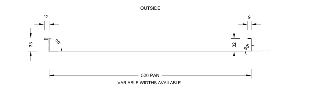
Roll-forming facility
Cover (mm)
Sheet width (mm)
Minimum Pitch
Roll-forming facility
AKL
Cover (mm)
525
Sheet width (mm)
523
Minimum Pitch
3º
Roll-forming facility
CHC
Cover (mm)
517
Sheet width (mm)
515
Minimum Pitch
3º
Roll-forming facility
INV
Cover (mm)
525
Sheet width (mm)
523
Minimum Pitch
3º
Note:
1. Cover width may vary based on manufacture location. Please consult you local Dimond branch for local cover dimensions
2. Minimum
pitch 3° - In snow loading zones N1-N5 (as
per Section 15 of NZS 3604), please contact the Dimond technical team at rooftech@dimond.co.nz for the minimum
pitch requirements.
Sheet Tolerances
Cover: ± 5mm - Sheet length: +10mm, -0mm (Steel)
Cover: +10mm, -15mm – Sheet length: +0mm, -15mm (Aluminium, VM Zinc and Copper)
MATERIAL CLADDING TESTING AND PREFORMANCE
Material Options
Steel
Aluminium
**VM Zinc
**Copper H/H
Thickness (BMT)
Steel
0.55
Aluminium
0.90
**VM Zinc
0.70
**Copper H/H
0.70
Nominal weight/lineal metre (kg/m)
Steel
2.77
Aluminium
1.48
**VM Zinc
3.06
**Copper H/H
3.84
Drape curved roof - min. radius (m)
Steel
40
Aluminium
70
**VM Zinc
40
**Copper H/H
40
Substrate required Min Thickness 12mm
Steel
Yes
Aluminium
Yes
**VM Zinc
Yes
**Copper H/H
Yes
Vented underlay required
Steel
R
Aluminium
R
**VM Zinc
R
**Copper H/H
R
1. Purlin spaces for curving (m)
Steel
0.600
Aluminium
0.600
**VM Zinc
0.600
**Copper H/H
0.600
2. Drip Edge /grab flashing is required
Steel
Yes
Aluminium
Yes
**VM Zinc
Yes
**Copper H/H
Yes
**Please contact Dimond Roofing 0800 DIMOND (0800346 663) for availability
(1) Recommended maximum purlin spacings at minimum radius
(2) Based on 1.1kN point load support but not intended for roof access.
R – Recommended i.e. Tyvek Metal but not limited too.
N/A – Not available.
Roll-forming facilities at: Auckland, Christchurch and Invercargill
Sheet lengths: Eurotray® is custom run to order.
Where long sheets are used, consideration must be given to:
- Special transportation licences
- Should be run on-site
- Site access for special lifting equipment
- Fixing techniques to accommodate thermal expansion
Oil Canning
Oil Canning is the visible waviness in the flat areas of metal roofing and walling. Oil canning produces an aesthetic effect inherent in standing seam tray profiles and profiles/flashings with wide flat elements. It does not cause detriment to product performance.
Oil canning can occur during the forming and installation processes and during thermal expansion of the roof sheeting during its life cycle. The effect can be more or less pronounced depending on differing light and sun angle conditions and the coating gloss levels.
For fully supported standing seam tray profiles, oil canning can be reduced by the vented roof underlay (e.g. Tyvek Metal), in addition, backer rods under the tray can also be used.
There are several options to reduce the oil canning effect in tray-type profiles and flashings, for example,
a) increasing the thickness of the material,
b) using stiffening swages in wide flat elements and
c) limiting flat elements to less than 150mm width.
For further information, please refer to the New Zealand Metal Roof and Wall Cladding Code of Practice, Section 12.3.
Fastener Design
Fastener Design
The durability of the fasteners should equal or exceed that of the material being fastened, and the fastener metal or coating must be compatible with the cladding material if in contact. Refer to NZS E2/AS1 table 20 for compatibility requirements.
The minimum embedment of 30mm is the requirement for screws fixing into timber and minimum of three threads to pass through steel. When fastening through cavity battens, thermal break materials etc ensure the length of the screw is increased to accommodate the extra material.
Common Fastener Lengths – Roof Cladding – 12mm Plywood substrate (STD)
Cladding Material
Timber Purlins (mm)
Timber Purlins with 20mm (nom.) Cavity batten
Steel Purlins up to 2.5mm (minimum 3 threads) (mm)
Steel Purlins up to 2.5mm (minimum 3 threads) (mm) With 20mm (nom.) Cavity batten
Steel
Timber Purlins (mm)
8g x 50 304 stainless steel
Timber Purlins with 20mm (nom.) Cavity batten
8g x 65 304 stainless steel
Steel Purlins up to 2.5mm (minimum 3 threads) (mm)
8g x 30 304 c/s stainless steel
Steel Purlins up to 2.5mm (minimum 3 threads) (mm) With 20mm (nom.) Cavity batten
8g x 50 304 c/s stainless steel
Aluminium
Timber Purlins (mm)
8g x 50 304 stainless steel
Timber Purlins with 20mm (nom.) Cavity batten
8g x 65 304 stainless steel
Steel Purlins up to 2.5mm (minimum 3 threads) (mm)
8g x 30 304 c/s stainless steel
Steel Purlins up to 2.5mm (minimum 3 threads) (mm) With 20mm (nom.) Cavity batten
8g x 50 304 c/s stainless steel
VM Zinc
Timber Purlins (mm)
8g x 50 304 stainless steel
Timber Purlins with 20mm (nom.) Cavity batten
8g x 65 304 stainless steel
Steel Purlins up to 2.5mm (minimum 3 threads) (mm)
8g x 30 304 c/s stainless steel
Steel Purlins up to 2.5mm (minimum 3 threads) (mm) With 20mm (nom.) Cavity batten
8g x 50 304 c/s stainless steel
Copper
Timber Purlins (mm)
8g x 50 304 stainless steel
Timber Purlins with 20mm (nom.) Cavity batten
8g x 65 304 stainless steel
Steel Purlins up to 2.5mm (minimum 3 threads) (mm)
8g x 30 304 c/s stainless steel
Steel Purlins up to 2.5mm (minimum 3 threads) (mm) With 20mm (nom.) Cavity batten
8g x 50 304 c/s stainless steel


Can be installed as a wall cladding with a substrate over vented cavity battens
Common Fastener Lengths – Roof Cladding – 12mm Plywood substrate (STD)
Cladding Material
Timber Dwangs (mm)
Steel Girts up to 2.5mm (mm)
Steel - Direct fix
Timber Dwangs (mm)
N/A
Steel Girts up to 2.5mm (mm)
N/A
Steel - On 20mm (nom.) Cavity Batten
Timber Dwangs (mm)
8g x 50 304 c/s stainless steel
Steel Girts up to 2.5mm (mm)
8g x 45 304 c/s stainless steel
Aluminium - Direct Fix
Timber Dwangs (mm)
N/A
Steel Girts up to 2.5mm (mm)
N/A
Aluminium- On 20mm (nom.) Cavity Batten
Timber Dwangs (mm)
8g x 50 304 c/s stainless steel
Steel Girts up to 2.5mm (mm)
8g x 45 304 c/s stainless steel
VM Zinc - Direct fix
Timber Dwangs (mm)
N/A
Steel Girts up to 2.5mm (mm)
N/A
VM Zinc - On 20mm (nom.) Cavity batten
Timber Dwangs (mm)
8g x 50 304 c/s stainless steel
Steel Girts up to 2.5mm (mm)
8g x 45 304 c/s stainless steel
Copper - Direct fix
Timber Dwangs (mm)
N/A
Steel Girts up to 2.5mm (mm)
N/A
Copper - On 20mm (nom.) Cavity batten
Timber Dwangs (mm)
8g x 50 304 c/s stainless steel
Steel Girts up to 2.5mm (mm)
8g x 45 304 c/s stainless steel
N/A – Not available
Roof Load Span Tables
Clip Fixing Table NZMRM CoP 15.4.9A
Wind Zone
Purlin Centre
Low to Very High
Purlin Centre
600
Extra High
Purlin Centre
400
Provision for Expansion
- Non-ferrous tray roofing expands at about twice the rate of ferrous metals
- Supported angle or double standing seam profiles must be installed using a balance of sliding clips for expansion, and fixed clips to withstand gravity loads
- Positioning of clips depends on roof pitch, please refer to NZMRM CoP 15.4.13.3A www.metalroofing.org.nz.
Downloads
Featured Downloads
Product Drawings
Filters
Active Filters ()
Drawing Type
Document Format
- Drawings9 Files
- Roofing3 Files
- Horizontal Cladding3 Files
- Vertical Cladding3 Files
Similar products
Eurotray® Roll Cap
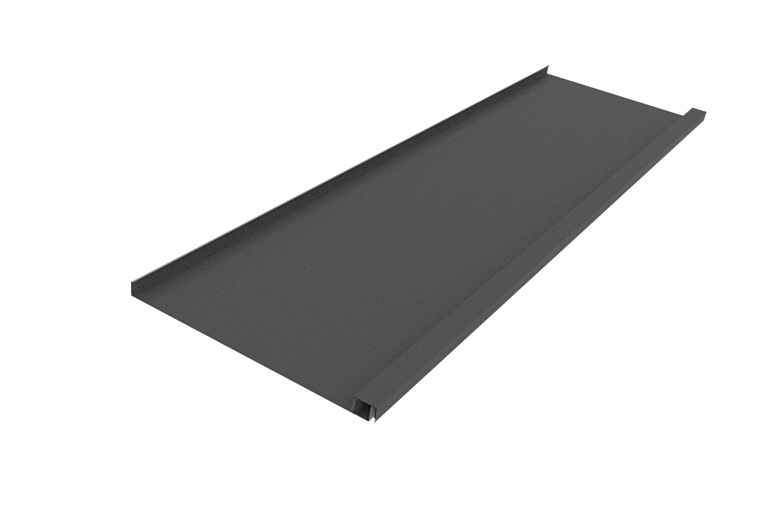
Roofing, Cladding Tray ProfileA New Zealand inspired design and the most popular profile of the Eurotray® family, Eurotray® Roll Cap offers clean lines and a uniquely robust and distinctive look. Visualise the traditional timber board and batten look and then imagine this in metal and you have Roll Cap. The profile is ideally suited to withstand New Zealand’s harshest climates.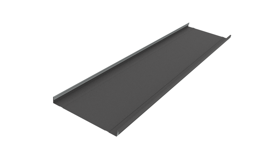
Heritage Tray®
Roofing, Cladding Tray ProfileHeritage Tray® markets itself as a refined, economical and flexible roofing profile. Heritage Tray® requires no additional plywood substrate thus reducing costs. Additionally, it can be roll formed on site, an attractive logistical option for larger construction projects.