Heritage Tray®
For Designer, Metallic and Gloss colours, download the ColorCote® special colours brochure.

465 sheet
Light Commercial
Christchurch
Invercargill
Heritage Tray® Performance
Evolving from the already popular and stylish Eurotray® family, Heritage Tray® markets itself as an elegant, economical and flexible roofing profile. Additionally, it can be roll-formed on-site, an attractive logistics option for larger construction projects.
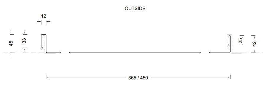

All dimensions given are nominal
Sheet Tolerances
Cover: ± 5mm - Sheet length: +10mm, -0mm (Steel)
Cover: +10mm, -15mm – Sheet length: +0mm, -15mm (Aluminium)
**Please contact Dimond Roofing on 0800 ROOFSPEC for availability
(1) Recommended maximum purlin spacings at minimum radius
(2) Only available in BMT's 0.54mm and 0.90mm
(3) Based on 1.1kN point load support, but not intended for roof access
N/A - Not available
Roll-forming facilities at: Auckland, Christchurch and Invercargill
Sheet lengths: : Heritage Tray® is custom run to order Also available to be manufactured on site.
Where long sheets are used, consideration must be given to:
- Special transportation licences for sheets over 25m
- Site access for special lifting equipment
- Fixing techniques to accommodate thermal expansion
OIL CANNING
Differential thermal movement between wide, flat surfaces and ribs or corners within a metal sheet can create a visual effect known as oil canning. This refers to the visible waviness or undulations in the flat sections of metal cladding, roofing, or walling. Oil canning is an inherent architectural characteristic of flat metal surfaces and is not indicative of any performance issues with the product.
It may occur during the forming and installation processes, as well as throughout the roof’s lifecycle due to thermal expansion. The visibility of oil canning can vary depending on lighting conditions, sun angles, and the gloss level of the coating.
For more details, please refer to Section 12.4 of the New Zealand Metal Roof and Wall Cladding Code of Practice.
Dimond Heritage Tray® Limit State Load / Span Capacity Chart
(span in mm, distributed ultimate load in kPa)
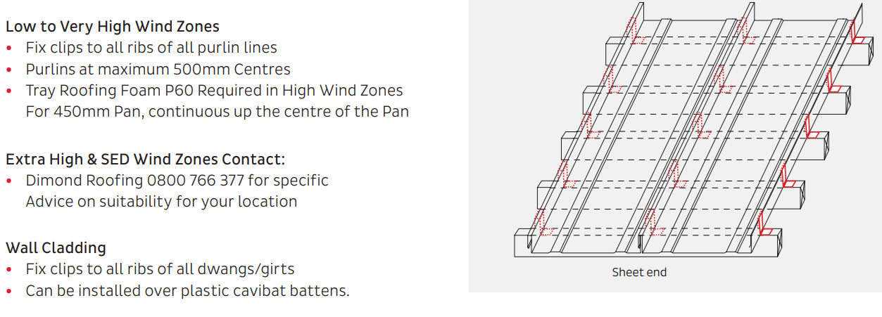
Fix clip to every purlin
Fix clip to every dwang/girt
Fix clip to every purlin
Fix clip to every dwang/girt
Notes:
1. In Restricted Access Roof and Non-Access Roof & Wall applications, spans exceeding the maximum values shown should not be used. The maximum spans for Restricted Access Roofs are based on static point load testing as a guide and are further limited by practical experience of roof performance under dynamic foot traffic loads. For Non-Access Roof & Wall applications, the maximum spans are limited to ensure satisfactory appearance for wall cladding.
2. Loads given are based on 1 clip/sheet/purlin.
3. Loads given are limited to a maximum of 4.7 kPa. If design requirements exceed this limit, contact Dimond for specific advice.
4. End span capacities given in this table are based on the end span being the same as the internal span.
5. Design Criteria for Limit State Capacities
a) Serviceability Limit State (SLS Design)
No deflection or permanent distortion that would cause unacceptable appearance, side lap leakage or water ponding, due to foot traffic point loads, inward or outward wind loads or snow loads.
b) Ultimate Limit State (ULS Design)
No pull through of fixings or fastener withdrawal resulting in sheet detachment due to wind up-lift (outward) loads.
6. System Design
The span capacity of the roofing or cladding profile is determined from the Load Span Table, using the section of the chart appropriate to the grade and type of material, and the category of serviceability selected from the two categories above. Serviceability loads have been derived by testing according to NZMRM procedures. To obtain an ultimate limit state load, we recommend factoring the serviceability load by 1.4 in line with NZMRM guidelines.
Note: The capacities given do not apply for cyclone wind conditions.
Serviceability Requirements
While these categories are provided for design guidance to meet the serviceability limit state criteria, foot traffic point load damage may still occur if point loads are placed carelessly.
Service Category
Refer to MRMCOP 3.7.4 Roof Traffic. The designer must consider the degree and type of foot traffic expected on a roof. The following equirements are subjective standards and must be considered in line with customer expectations, building use, and type. More robust design than specified below (such as reducing purlin spacing or adding protection from mechanical action) is required for roofs that are regularly accessed, used as staging by subsequent trades, or areas adjacent to access points, particularly step-down access.
7. Wind Pressure Guide
As a guide for non-specific design the following S.L.S. design loads in accordance with the MRM Roofing Code of Practice can be used for buildings less than 10m high, otherwise AS/NZS 1170.2 should be used Low wind zone = 0.68kPa, Medium wind zone = 0.93kPa, High wind zone = 1.32kPa, Very high wind zone = 1.72kPa and Extra high wind zone = 2.09kPa
Heritage Tray®Fastener Design
The durability of the fasteners should equal or exceed that of the material being fastened, and the fastener metal or coating must be compatible with the cladding material if in contact. Refer to NZS E2/AS1 table 20 for compatibility requirements.
The minimum embedment of 30mm is the requirement for screws fixing into timber and minimum of three threads to pass through steel. When fastening through cavity battens, thermal break materials etc ensure the length of the screw is increased to accommodate the extra material.
* When a substrate is used the fastener length will need to be adjusted to suit thickness
N/A – Not Available
Note: Use a minimum 75mm long driver to set the screw
Fastener Layout
N/A – Not available
Product Technical Statement
To help you get through the building consent process as quickly as possible, we have developed the Product Technical Statement (PTS) downloads to make it quick and easy for both Architects and Home Owners to access the documentation required.
The PTS downloads hold all of the information that the council requires for a building consent where Dimond product is specified.