Dimondek® 400
For Designer, Metallic and Gloss colours, download the ColorCote® special colours brochure.

412mm sheet
Light commercial
Hamilton
Wellington
Christchurch
Dimondek® 400 adds architectural interest to your roof, with its broad angular ribs and wide pans it brings modern styling to your roof. The concealed fix system provides a strong clean finish with no visible fixings. Ideally suited for modern contemporary homes, DD400 is the ultimate bold statement in roofs.
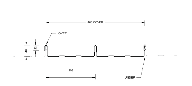
RECOMMENDED PRODUCT/DESIGN USE • Minimum Pitch: 3 degrees • Cover (mm): 405mm
• Applications: Residential / Industrial / Commercial Roofing and Wall Cladding
• Materials: Specified coating and material based on environmental conditions in accordance with E2/AS1.
Available in metallic coated and pre-painted steel in 0.40mm, 0.55mm and 0.75mm - Aluminium 0.90mm BMT (base material thickness). Matching translucent sheeting is available in G.R.P. (fibreglass)
• Material Thickness: Steel, 0.40mm, 0.55mm and 0.75mm – Aluminium 0.90mm
• Colours: Available in pre-painted ColorCote® ZinaCore™, MagnaFlow™ and MagnaFlow® COLORSTEEL® MAXAM™ and Altimate®
Refer to www.colorcote.co.nz and www.colorsteel.co.nz.
• Durability: All material selections must be compatible with the prevailing environmental conditions and adjacent materials. Areas not naturally exposed to rain will require scheduled maintenance.
All dimensions given are nominal
Sheet Tolerances
Sheet width: ±5mm
Sheet length: +10mm, –0mm. For horizontal wall cladding where notified at time of order of intended use, tighter tolerances can be achieved +3mm, –0mm.
*Dimondek 400 is available in Copper ex Auckland only, subject to coil availability.
**To achieve a high level of appearance on the completed roof, it is important that the purlin layout alignment is laid within the tolerances as stated in Section 2.4.2.3.1.
(1) Recommended maximum purlin spacing at minimum radius
(2) Based on 1.1kN point load support, but not intended for roof access.
(3) Product only available in ColorCote® MagnaFlow™ or Colorsteel® MAXX coated product range
n/a – not available
Roll-forming facilities for Dimondek® 400 at: Auckland, Hamilton, Wellington and Christchurch.
Sheet lengths: DD400 is custom run to order.
Where long sheets are used consideration must be given to:
- Special transportation licences for sheet lengths over 25m
- Site access for special lifting equipment
- Fixing techniques to accommodate thermal expansion. Refer Section 2.1.3.4. in Technical Manual
DD400 Limit State Load / Span Capacity
(span in mm, distributed ultimate loads in kPa)
Notes In Restricted Access Roof and Non-Access Roof & Wall applications, spans exceeding the maximum values shown should not be used. The maximum spans for Restricted Access Roofs are based on static point load testing as a guide and are further limited by practical experience of roof performance under dynamic foot traffic loads. For Non-Access Roof & Wall applications, the maximum spans are limited to ensure satisfactory appearance for wall cladding.
2. Loads given are based on clip fastening every rib at every purlin.
3. If design requirements exceed the loads given above, the push on Dimond wind clamps can be installed to double the wind uplift load.
4. N/R = not recommended.
5. For the purposes of serviceability design, the serviceability limit, limited by permanent rib deformation, occurs essentially at the same load as ultimate failure which is the point of disengagement of the roof with the clip.
6. End span capacities given in this table are based on the end span being 2:3 ratio of the internal span.
7. Design Criteria for Limit State Capacities a) Serviceability Limit State (SLS Design) No deflection or permanent distortion that would cause unacceptable appearance, side lap leakage or water ponding, due to foot traffic point loads, inward or outward wind loads or snow loads. b) Ultimate Limit State (ULS Design) No pull through of fixings or fastener withdrawal resulting in sheet detachment due to wind up-lift (outward) loads.
8. System Design The span capacity of the roofing or cladding profile is determined from the Load Span Table, using the section of the chart appropriate to the grade and type of material, and the category of serviceability selected from the two categories above. Ultimate limit state loads have been derived by testing according to NZMRM procedures.
Note: The capacities given do not apply for cyclone wind conditions. Serviceability Requirements While these categories are provided for design guidance to meet the serviceability limit state criteria, foot traffic point load damage may still occur if point loads are placed carelessly. Service Category Refer to MRMCOP 3.7.4 Roof Traffic. The designer must consider the degree and type of foot traffic expected on a roof. The following requirements are subjective standards and must be considered in line with customer expectations, building use, and type. More robust design than specified below (such as reducing purlin spacing or adding protection from mechanical action) is required for roofs that are regularly accessed, used as staging by subsequent trades, or areas adjacent to access points, particularly step-down access.
9. Wind Pressure Guide As a guide for non-specific design the following S.L.S. design loads in accordance with the MRM Roofing Code of Practice can be used for buildings less than 10m high, otherwise AS/NZS 1170.2 should be used Low wind zone = 0.68kPa, Medium wind zone = 0.93kPa, High wind zone = 1.32kPa, Very high wind zone = 1.72kPa and Extra high wind zone = 2.09kPa.
DIMONDEK® 400 CLIP Used to secure by pushing the profile down onto it until it clicks into place. The Dimondek® 400 is designed to fix over the previously laid male under rib and centre rib of the sheet to be laid.
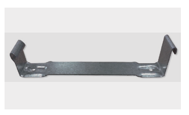
Clip Material Usually manufactured from either 1. As standard unpainted 1.15mm thick coil with galvanised coating to 275 g/m2 2. Coated for increased durability. Nylon coated over galvanised. Colour may vary between Bright blue or light grey depending on supply. During a salt fog test after 2000 hours this coat showed no sign of degradation. Must be used with Aluminum roofing 3. Other material, such as brass clips to suit a copper roof, can be manufactured to customer order. The brass is 1.2mm thick and is 1/2 hard brass.
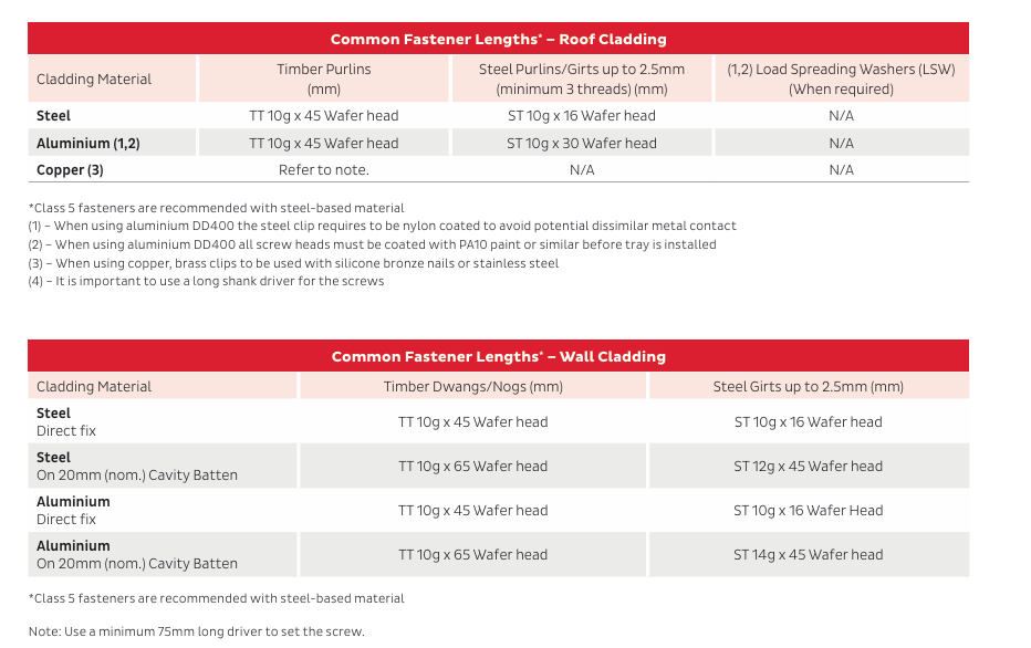
FASTENERS
The durability of the fasteners should equal or exceed that of the material being fastened, and the fastener metal or coating must be compatible with the cladding material if in contact. Refer to NZS E2/AS1 table 20 for compatibility requirements. The minimum embedment of 30mm is the requirement for screws fixing into timber and minimum of three threads to pass through steel. When fastening through cavity battens, thermal break materials etc ensure the length of the screw is increased to accommodate the extra material.
The Limit State Load / Span Capacity Chart is based on every rib being clip fastened to every purlin or girt.
Design Example
Restricted access roof, 0.55mm G300 steel Dimondek 400 has a maximum end span of 1100mm and a maximum internal span of 1600mm. The following distributed load capacities apply.
Product Technical Statement
To help you get through the building consent process as quickly as possible, we have developed the Product Technical Statement (PTS) downloads to make it quick and easy for both Architects and Home Owners to access the documentation required.
The PTS downloads hold all of the information that the council requires for a building consent where Dimond product is specified.