Dimondek® 630
For Designer, Metallic and Gloss colours, download the ColorCote® special colours brochure.

675mm sheet
Hamilton
Dimondek ® 630 Performance
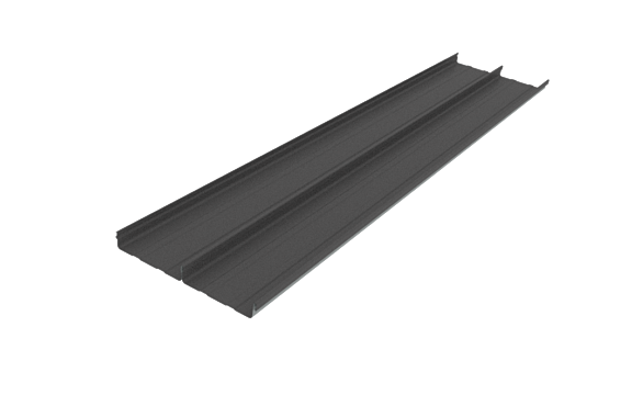
Dimondek®630 is a revolutionary concealed clip profile, which can be manufactured onsite in lengths up to 100m. Dimondek® 630’s onsite manufacturing allows for gutter to gutter sheets in a continuous draped curve. The greater span capability means fewer purlins are required and it’s faster to install. With no screw holes through the roof, leaks are virtually eliminated meaning your roof lasts longer. With improved lifecycle costs Dimondek® 630 is the most economical concealed clip roofing profile on the market.
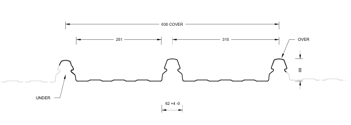
All dimensions given are nominal
Sheet Tolerances
Cover: ± 5mm - Sheet length: +10mm, -0mm (steel)
(1) Recommended maximum purlin spacing at minimum radius
(2) N/A
(3) Based on 1.1kN point load support, but not intended for roof access.
N/A – not available
Roll-forming facilities at: Mobile machine based in Hamilton and can moved to site – Roll to Roof – when/if required.
Crimp curving facility location: N/A
Sheet lengths: Dimondek® 630 is custom run to order.
Where long sheets are used consideration must be given to:
- Special transportation licences for sheet lengths over 25m
- Site access for special lifting equipment
- Fixing techniques to accommodate thermal expansion.
DD630 Limit State Load / Span Capacity
(span in mm, distributed ultimate loads in kPa)
Notes
- In Restricted Access Roof and Non-Access Roof & Wall applications, spans exceeding the maximum values shown should not be used. The maximum spans for Restricted Access Roofs are based on static point load testing as a guide and are further limited by practical experience of roof performance under dynamic foot traffic loads. For Non-Access Roof & Wall applications, the maximum spans are limited to ensure satisfactory appearance for wall cladding.
- Loads given are based on clip fastening every rib at every purlin.
- Loads given are limited to a maximum of 2.6 kPa. If design requirements exceed this limit, contact Dimond for specific advice.
- Spans beyond 3.6m are not recommended.
- For the purposes of serviceability design, the serviceability limit, limited by permanent rib deformation, occurs essentially at the same load as ultimate failure which is the point of disengagement of the roof with the clip.
- End span capacities given in this table are based on the end span being 2/3 of the internal span.
- Design Criteria for Limit State Capacities
- Serviceability Limit State (SLS Design)
No deflection or permanent distortion that would cause unacceptable appearance, side lap leakage or water ponding, due to foot traffic point loads, inward or outward wind loads or snow loads. - Ultimate Limit State (ULS Design)
No pull through of fixings or fastener withdrawal resulting in sheet detachment due to wind up-lift (outward) loads.
- Serviceability Limit State (SLS Design)
- System Design
The span capacity of the roofing or cladding profile is determined from the Load Span Table, using the section of the chart appropriate to the grade and type of material, and the category of serviceability selected from the two categories above. Serviceability loads have been derived by testing according to NZMRM procedures. To obtain an ultimate limit state load, we recommend factoring the serviceability load by 1.4 in line with NZMRM guidelines.
Note: The capacities given do not apply for cyclone wind conditions. - Serviceability Requirements
While these categories are provided for design guidance to meet the serviceability limit state criteria, foot traffic point load damage may still occur if point loads are placed carelessly.
Service Category
Refer to MRMCOP 3.7.4 Roof Traffic. The designer must consider the degree and type of foot traffic expected on a roof. The following equirements are subjective standards and must be considered in line with customer expectations, building use, and type. More robust design than specified below (such as reducing purlin spacing or adding protection from mechanical action) is required for roofs that are regularly accessed, used as staging by subsequent trades, or areas adjacent to access points, particularly step-down access. - Wind Pressure Guide
As a guide for non-specific design the following S.L.S. design loads in accordance with the MRM Roofing Code of Practice can be used for buildings less than 10m high, otherwise AS/NZS 1170.2 should be used
Low wind zone = 0.68kPa, Medium wind zone = 0.93kPa, High wind zone = 1.32kPa, Very high wind zone = 1.72kPa and Extra high wind zone = 2.09kPa.
FASTENERS
The durability of the fasteners should equal or exceed that of the material being fastened, and the fastener metal or coating must be compatible with the cladding material if in contact. Refer to NZS E2/AS1 table 20 for compatibility requirements.
The minimum embedment of 30mm is the requirement for screws fixing into timber and minimum of three threads to pass through steel. When fastening through cavity battens, thermal break materials etc ensure the length of the screw is increased to accommodate the extra material.
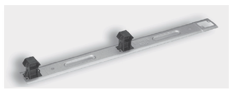
The Dimondek® 630 perimeter clip must always be used over the first rib and clip on the first laid sheet.The Limit State Load / Span Capacity Chart is based on every rib being clip fastened to every purlin.
Design Example
Restricted access roof, 0.55mm G550 steel Dimondek® 630 has a maximum end span of 2800mm and a maximum internal span of 4200mm. The following distributed load capacities apply.
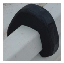
Dimond 630® Wind Clamp
Dimondek 630® wind clamps are required to be installed over all ribs at all purlin locations where design wind loads are higher than those shown on the Dimondek 630® Load/Span chart. Call our Technical Team on 0800 766377 for advice.
Dimond 630® Clip
Product Technical Statement
To help you get through the building consent process as quickly as possible, we have developed the Product Technical Statement (PTS) downloads to make it quick and easy for both Architects and Home Owners to access the documentation required.
The PTS downloads hold all of the information that the council requires for a building consent where Dimond product is specified.