LT7®
For Designer, Metallic and Gloss colours, download the ColorCote® special colours brochure.
933mm sheet
Light Commercial
Commercial
Invercargill
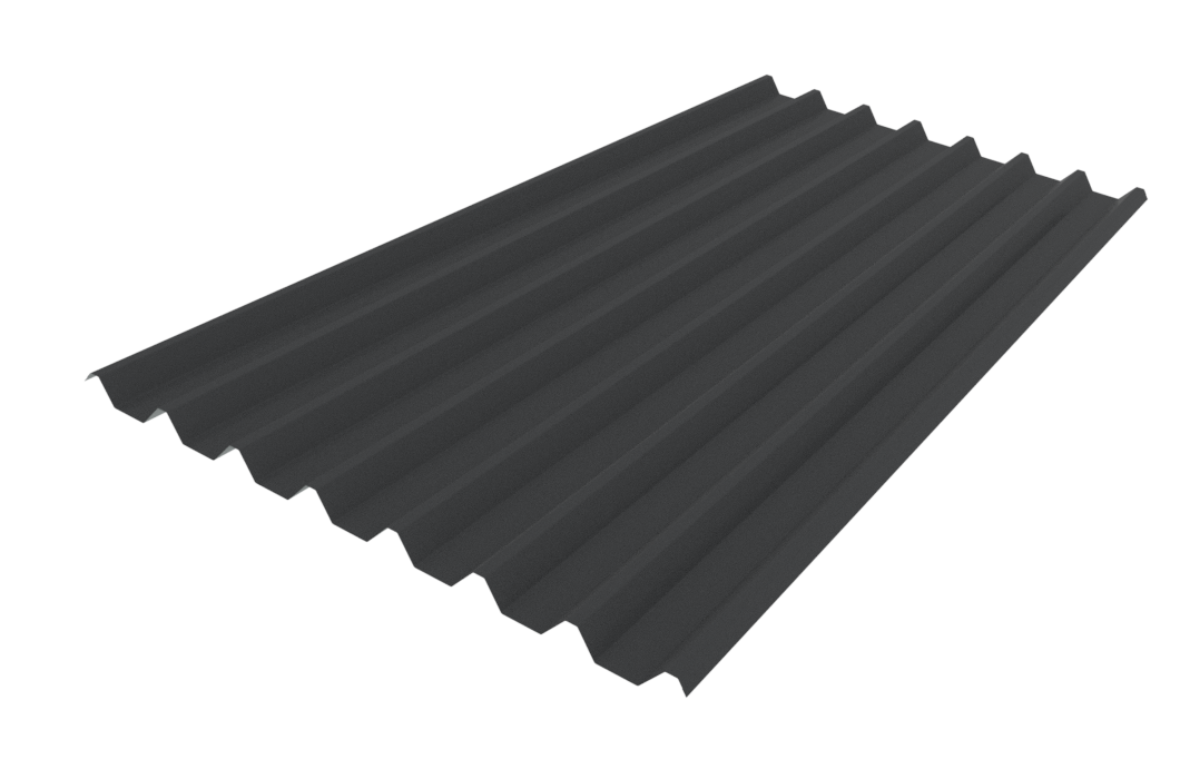
Designed for applications where protection from severe climatic conditions and maximum structural economy is required, the strong section properties of LT7® allow for wider purlin and girt spacings which add extra economy to building projects. It also has excellent water shedding characteristics as well as being perfect for low pitch roofs.
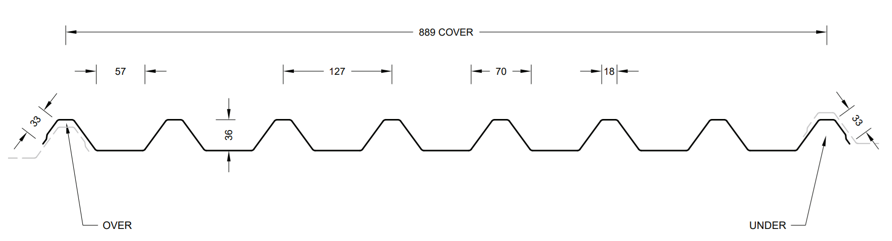
All dimensions given are nominal
(1) Recommended maximum purlin spacings at minimum radius
(2) N/A
(3) Based on 1.1kN point load support, but not intended for roof access
N/R – Not recommended
N/A – Not available.
Roll-forming facility location: Wellington and Invercargill
Crimp curving facility location: Hamilton and Christchurch
Manufacturing location for DuraClad®: Auckland
Sheet lengths: LT7® is custom run to order.
Where long sheets are used, consideration must be given to:
- Special transportation licences for sheet lengths over 25m
- Site access for special lifting equipment
- Fixing techniques to accommodate thermal expansion
DIMOND LT7® LIMIT STATE LOAD / SPAN CAPACITY CHART
(span in mm, distributed serviceability loads in kPa)
Notes
- In Restricted Access Roof and Non-Access Roof & Wall applications, spans exceeding the maximum values shown should not be used. The maximum spans for Restricted Access Roofs are based on static point load testing as a guide and are further limited by practical experience of roof performance under dynamic foot traffic loads. For Non-Access Roof & Wall applications, the maximum spans are limited to ensure satisfactory appearance for wall cladding
- Loads given are based on 4 screw fasteners/sheet/purlin.
- Loads given are limited to a maximum of 3.5kPa. If design requirements exceed this limit, Contact Dimond for specific advice.
- Duraclad®
- Serviceability Limit State Load are not applicable to Duraclad® material, as it does not experience permanent deformation
- System must include Safety Mesh it intended for use as a Restricted-Access roof. Refer Section 2.2.1.8 of Technical Manual - N/R = not recommended
- End span capacities given in this table are based on the end span being 2:3 ratio of the internal span.
- Design Criteria for Limit State Capacities
- Serviceability Limit State (SLS Design)
No Deflection or permanent distortion that would cause unacceptable appearance, side lap leakage or water ponding, due to foot traffic point loads, inward or outward wind loads or snow loads. - Ultimate Limit State (ULS Design)
No pull through of fixings or fasteners withdrawal resulting in sheet detachment due to wind up-lift (outward) loads.
- Serviceability Limit State (SLS Design)
- System Design
The span capacity of the roofing or cladding profile is determined from the Load Span Table, using the section of the chart appropriate to the grade and type of material, and the category of serviceability selected from the two categories above. Serviceability loads have been derived by testing according to NZMRM procedures. To obtain an ultimate limit state load, we recommend factoring the serviceability load by 1.4 in line with NZMRM guidelines.
Note: The capacities given do not apply for cyclone wind conditions.
Serviceability Requirements
While these categories are provided for design guidance to meet the serviceability limit state criteria, foot traffic point load damage may still occur if point loads are placed carelessly
Service Category
Refer to MRMCOP 3.7.4 Roof Traffic. The designer must consider the degree and type of foot traffic expected on a roof. The following equirements are subjective standards and must be considered in line with customer expectations, building use, and type. More robust design than specified below (such as reducing purlin spacing or adding protection from mechanical action) is required for roofs that are regularly accessed, used as staging by subsequent trades, or areas adjacent to access points, particularly step-down access
- Wind Pressure Guide
As a guide for non-specific design the following S.L.S. design loads in accordance with the MRM Roofing Code of Practice can be used for buildings less than 10m high, otherwise AS/NZS 1170.2 should be used Low wind zone = 0.68kPa, Medium wind zone = 0.93kPa, High wind zone = 1.32kPa, Very high wind zone = 1.72kPa and Extra high wind zone = 2.09kPa
LT7® Fastener Design
The durability of the fasteners should equal or exceed that of the material being fastened, and the fastener metal or coating must be compatible with the cladding material if in contact. Refer to NZS E2/AS1 table 20 for compatibility requirements.
The minimum embedment of 30mm is the requirement for screws fixing into timber and minimum of three threads to pass through steel. When fastening through cavity battens, thermal break materials etc ensure the length of the screw is increased to accommodate the extra material
*Class 5 fasteners are recommended with steel-based material
(1) – When using LSW increase fastener length by 10mm
(2) - When using LSW pre-drill a 10mm oversized hole to accommodate the EPDM washer
*Class 5 fasteners are recommended with steel-based material.
**Stainless steel fasteners require to be separated from aluminium.
Use in serviceability categories (1) or (2) can allow the reduction of fasteners to an average of 2 screw fasteners/sheet/ purlin. If this is done, the distributed load capacities given in the chart should be reduced using a multiplying factor of 0.5.
Long spans may require the specification and use of side lap stitching screws – see Section 2.3.2C Installation Information: Layout and Fastening.
Design Examples
Restricted access roof, 0.55mm G550 steel LT7® has a maximum end span of 1900mm and a maximum internal span of 2900mm.
The following distributed load capacities apply.
Fixing Layout Options


Product Technical Statement
To help you get through the building consent process as quickly as possible, we have developed the Product Technical Statement (PTS) downloads to make it quick and easy for both Architects and Home Owners to access the documentation required.
The PTS downloads hold all of the information that the council requires for a building consent where Dimond product is specified.